Pressurised Heating Buffer Tank 10–500 m³ — PED 2014/68/EU Certified

10–500 m³ — PED 2014/68/EU Certified
Pressurized Heating Buffer Tanks are pressure vessels designed and manufactured in accordance with the EU Pressure Equipment Directive PED 2014/68/EU and EN 13445 (Unfired Pressure Vessels).
They are the correct choice whenever the Thermal Energy Storage Tank must form part of a closed, pressurised heating or cooling circuit — the standard architecture for modern industrial or commercial electrical boiler or heat pump heating systems.
WTS pressurized Heating Buffer Tanks are:
- Factory-built, vertical, cylindrical, above-ground, heat-insulated, stainless steel welded pressure vessels.
- Designed to PED 2014/68/EU.
- Manufactured and tested per EN 13445 with a full documentation package.
- Thermally insulated per EN 17956:2024 Class A insulation standard.
- Designed for optimal stratification and energy efficiency.
- Designed with Earthquake and Wind loads for the hardest EU conditions as standard.
- Supplied with CE marking, Declaration of Conformity, and test certificates.
- Pre-fitted with safety relief valves, vacuum relief valves, pressure sensor, and temperature sensor as standard.
- Designed for a heating carrier temperature of +95 °C, as standard, and available up to +130 °C as an option.
- Ready for immediate direct integration into customer project design with 3D model, P&ID, drawing, and datasheet package included.
- Available in all stainless grades listed below; duplex grades recommended for aggressive water chemistries.
- Available with different connections and scope of delivery.
Offered Heating Buffer Tanks Volumes and Pressure Ratings
Vertical Above-Ground Heating Buffer Tanks for Operating Pressure of 3 bar
| Tank Model | Nominal Capacity, m³ | Nominal Diameter, mm | Approx. Height (without insulation), mm |
Approx. Empty Weight (without insulation), kg |
|---|---|---|---|---|
| TES-010-3-H | 10 | 1500 | 6541 | 900 |
| TES-020-3-H | 20 | 1850 | 8166 | 1750 |
| TES-030-3-H | 30 | 2050 | 9733 | 2300 |
| TES-050-3-H | 50 | 2450 | 11378 | 4050 |
| TES-080-3-H | 80 | 3050 | 11610 | 6200 |
| TES-100-3-H | 100 | 3050 | 14590 | 7700 |
| TES-150-3-H | 150 | 3400 | 17706 | 10400 |
| TES-200-3-H | 200 | 3750 | 19331 | 14600 |
| TES-300-3-H | 300 | 4600 | 19660 | 20900 |
| TES-400-3-H | 400 | 5260 | 19916 | 27300 |
| TES-500-3-H | 500 | 5260 | 24386 | 33200 |
**The standard scope of delivery applies a design minimum ambient temperature of −30 °C.
Vertical above-ground Heating Buffer Tanks for operating pressure 6 bar
| Tank Model | Nominal Capacity, m³ | Nominal Diameter, mm | Approx. Overall Height (without insulation), mm |
Approx. Empty Weight (without insulation), kg |
|---|---|---|---|---|
| TES-010-6-H | 10 | 1500 | 6541 | 1700 |
| TES-020-6-H | 20 | 1850 | 8166 | 3100 |
| TES-030-6-H | 30 | 2050 | 9733 | 4050 |
| TES-050-6-H | 50 | 2450 | 11378 | 7250 |
| TES-080-6-H | 80 | 3050 | 11610 | 11300 |
| TES-100-6-H | 100 | 3050 | 14590 | 14100 |
| TES-150-6-H | 150 | 3400 | 17706 | 20800 |
| TES-200-6-H | 200 | 3750 | 19331 | 27050 |
| TES-300-6-H | 300 | 4600 | 19660 | 41800 |
| TES-400-6-H | 400 | 5260 | 19916 | 54700 |
| TES-500-6-H | 500 | 5260 | 24386 | 66450 |
**The standard scope of delivery applies a design minimum ambient temperature of −30 °C.

Delivery Options
Depending on the specific requirements of the customer’s project, Heating Buffer Tanks can be supplied in a wide range of configurations and technical arrangements. Factors such as storage capacity, operating pressure, hydraulic integration, temperature levels, installation site conditions, and decarbonization strategy influence the final design. To ensure optimal performance, safety, and compatibility with district heating systems, renewable energy sources, and industrial heating applications, both standard and optional equipment can be selected. The table below outlines the available delivery options, highlighting standard components and configurable items that can be adapted to meet individual project needs.
| # | Item | Standard | Option |
|---|---|---|---|
| 1 | Manhole | 1 | On request |
| 2 | Hot Charging Inlet flange | 1 | 1 |
| 3 | Hot Discharging Outlet flange | 1 | – |
| 4 | Cold Charging Inlet flange | 1 | 1 |
| 5 | Cold Discharging Outlet flange | 1 | – |
| 6 | Drain flange | 1 | 1 |
| 7 | Vent flange | 1 | 1 |
| 8 | Vacuum Relief Valve flange | 2 | On request |
| 9 | Pressure Safety Valve flange | 2 | On request |
| 10 | Pressure sensor flange | 1 | On request |
| 11 | Temperature sensor flange | 1 | On request |
| 12 | Lifting Eyes | 2 | On request |
| 13 | Nozzle PN rating | PN16 | On request |
| 14 | Nozzle Elevations | Standard | On request |
| 15 | Nozzle Arrangement | Standard | On request |
| 16 | Surface treatment | Pickling and passivation | On request |
| 17 | Template for anchor bolts supplied prior to foundation construction | 1 | On request |
Insulation & Finishing
- We provide high-performance Polyurethane (PUR) and Mineral Wool (MW) insulation solutions, available through in-factory application or on-site installation to suit your specific tank dimensions and project needs.
- Our TES-H series thermal energy storage models are certified to meet Class A thermal performance (or custom requirements) in accordance with EN 17956:2024 standards.
- Metal cladding (thickness 1.0–1.5 mm) in the required color, or aluminum or stainless steel outer cladding (AISI 304, thickness 0.6–1.0 mm), providing weather protection and a clean, aesthetic appearance.
- Colour-coded nozzle labelling, nameplates, and CE marking plate fitted as standard.
Standard Documentation Package
- Compliance: CE Declaration of Conformity (PED 2014/68/EU).
- Testing: Hydrostatic pressure test reports and NDT (Non-Destructive Testing) records (e.g., X-ray, Dye Pen).
- Traceability: EN 10204 3.1 Material Certification for all pressure-retaining parts.
- Technical Drawings: Detailed GA drawings, P&ID, and Nozzle Schedules.
- Maintenance: Comprehensive Operation & Maintenance (O&M) Manual.
- 3D model (file extension *.ifc).
Model Selection Guide
TES-[Capacity,m3]-[Max Operating Pressure, bar]-[Temp Application].
Examples:
- TES-100-6-H: 100 m3 vessel, 6 bar design pressure, optimized for Hot Water storage.
- TES-300-3-C: 300 m3 vessel, 3 bar design pressure, optimized for Chilled Water storage.
- TES-050-ATM-C: 50 m3 tank, Atmospheric design, optimized for Chilled Water storage.
- TES-150-ATM-H: 150 m3 tank, Atmospheric design, optimized for Hot Water storage.
What Decarbonization Problem Does an Industrial Heating Buffer Tank Solve?
The TOP-7 most important points for the current decarbonisation picture:
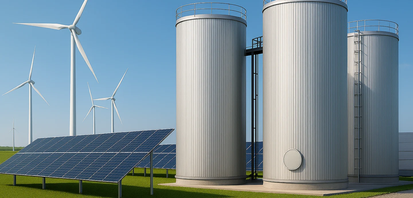
- Wind and solar are now the cheapest sources of electricity on Earth — but their value collapses during periods of excess generation.
- Industrial factories are unable to tap into this low-cost clean energy: they run 24/7 while renewable sources are intermittent. Electricity is cheapest in off-peak hours, typically about 5–8 hours per day.
- The primary obstacle to fully developing wind and solar energy is the insufficient capacity for energy storage in the power system.
- EU Industry and District Heating consume fossil fuels for approximately 75% of energy generation in thermal energy form.
- Approximately 30% of consumed thermal energy in the EU is low-temperature thermal energy — heating media temperature up to 95 °C. The most cost-effective heat medium for low-temperature thermal storage is clarified, demineralised water.
- Thermal Energy Storage tanks — Heating Buffer Tanks — are a cost-effective and scalable method of converting intermittent electricity to always-available thermal energy, charging during off-peak hours at lowest electricity cost.
- The core challenge is how to store large amounts of low-temperature thermal energy efficiently over extended periods.
The solution is an industrial heating buffer tank — a thermally insulated pressure vessel designed to store excess heat in the form of hot pressurised water, effectively bridging the gap between heat generation and fluctuating heat demand.
An industrial heating buffer tank solves the decarbonization problem of mismatched timing between clean heat production and variable heat demand—enabling efficient electrification, eliminating fossil peaking, and maximizing the use of renewable and waste heat.
Industrial heating buffer tanks are the most efficient way to store low-temperature thermal energy at scale, delivering the lowest life-cycle cost over decades of operation.
With WTS prefabricated buffer tanks, heating projects benefit from simplified and faster design, rapid installation, proven reliability, and long-term performance in commercial and district heating networks.
Applications in Industrial & Commercial Heating Systems
Decarbonising industrial, commercial, and district heat is one of the EU’s most pressing engineering challenges.
Heat pumps, electric boilers, solar thermal systems, biomass boilers, and waste-heat recovery systems can all displace fossil fuels for low-temperature applications — but only when paired with correctly specified thermal energy storage. Without adequate buffer volume, the economics collapse and efficiency targets are missed.
Western Technological Solutions (WTS) manufactures factory-built stainless steel pressurized heating buffer tanks with working volumes from 10 m³ to 500 m³.
Every unit is pre-designed, instrumented, and tested in our Klaipeda production facility — then delivered and commissioned as a complete, ready-to-operate system.
Our industrial tank insulation is installed in-house or on-site to accommodate various tank sizes and project requirements.
We serve HVAC contractors, EPC contractors, district heating operators, industrial and commercial heat consumers, solar thermal developers, and energy companies across Scandinavia and the EU.
Our pressurized heating buffer tanks comply with PED 2014/68/EU, manufactured under EN 13445, with insulation performance certified to EN 17956:2024 Class A — the highest efficiency grade available.
Primary Applications – Heating Buffer Tanks
Electric Boiler & Demand-Response TES: Pressurized buffer tanks paired with electrode or resistance boilers allow operators to shift electrical load to off-peak windows, dramatically reducing energy costs and supporting grid balancing under REPowerEU targets.
Heat Pump Systems: Large-scale commercial, industrial, and district heating heat pumps (air-source, ground-source, sea-source) require buffer vessels to decouple the heat pump compressor cycle from the distribution network, reducing start-stop cycling and extending compressor life.
Biomass & Waste-Heat Boilers: Biomass combustion systems produce heat at variable rates. Buffer tanks decouple generation from demand, prevent short-cycling, and allow the boiler to run at peak efficiency.
District Heating Substations & Peak-Shaving: Municipal and industrial district heating networks use pressurized buffer tanks at node level for peak-shaving, emergency heat reserve, and hydraulic decoupling of network zones.
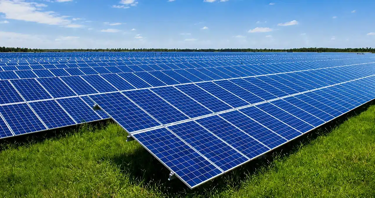
Solar Thermal Arrays: Large-aperture solar thermal collectors produce heat intermittently. Pressurized buffer tanks store daytime solar gain for evening/night load coverage in industrial process heat and district heating applications.
Industrial Process Heat (≤ 95 °C): Food & beverage, pharmaceutical, textile, and chemical plants requiring stable process hot water benefit from buffer vessels to absorb demand spikes without increasing boiler/heat pump capacity.
Why Pressurized Buffer Tanks Are Essential?
A key factor in understanding why Pressurized Heating Buffer Tanks are essential lies in the design and operational requirements of modern closed-loop heating networks — centralised HVAC, district heating, solar thermal, and commercial systems.
Today’s most centralised and district heating systems are sealed, pressurized, closed-loop systems. There are two main technical drivers:
1. High Operating Temperature Range
Closed-loop heating networks can operate at supply temperatures of 95–130 °C. Atmospheric open tanks cannot withstand these temperatures. Pressurized tanks maintain the water in a liquid state near or above 100 °C, enabling the heating system to extract maximum energy density from the thermal store.
2. Water Quality Preservation
The heat-transfer medium must comply with strictly regulated water quality standards. The closed-loop system must remain completely isolated from the atmosphere at all times.
Any contact between the heat-transfer medium and air causes:
- Increased dissolved oxygen, leading to accelerated internal corrosion of pipework and heat exchangers.
- Increased dissolved CO₂, resulting in pH reduction and further corrosion acceleration.
- Destabilisation of conductivity, corrosion inhibitor concentration, and thermal-hydraulic design parameters.
- Formation of sludge and solid deposits.
- Reduced heat-transfer efficiency.
- Increased maintenance requirements and operational risks.
- Shortened service life of system components.
Controlled media parameters in closed-loop systems:
Oxygen content | CO₂ concentration | pH level | Conductivity / TDS
Corrosion inhibitor concentration | Chemical stability of heat-transfer medium
For these reasons, pressurized heating buffer tanks offer the most reliable and cost-effective solution for thermal energy storage in closed-loop district heating systems.
By maintaining system pressure and preventing air ingress, they preserve water quality, minimize corrosion risks, and ensure long-term operational reliability.
Stainless Steel Material Options and Comparison with Carbon Steel
WTS manufactures pressurized heating buffer tanks in a range of austenitic and duplex stainless steel grades.
The choice of material is defined by the chloride concentration and other parameters of the heating medium quality requirements for closed-loop heating networks. This directly affects corrosion resistance, weldability, long-term maintenance costs, and overall service life.
Recommended grade for standard district heating buffer tanks up to +95 °C:
Lean duplex stainless steel EN 1.4162 (LDX 2101) — provides a good balance of corrosion resistance, weldability, mechanical strength, and cost for commercial and district heating applications.
- EN 1.4162 offers significantly higher resistance to chloride stress corrosion cracking (SCC) than austenitic grades such as 304L and is generally comparable to 316L in pitting resistance under moderate chloride conditions.
- For neutral or slightly alkaline district heating water at temperatures up to ~95 °C, EN 1.4162 is commonly considered suitable when chloride concentration is kept low (typically ≤ 100 ppm), assuming good water chemistry control and absence of crevice-prone design details.
- Like all lean duplex grades, its pitting and general corrosion rate increase with temperature and chloride level, so prolonged exposure to chloride-rich water or poor oxygen control should be avoided.
Why stainless steel over carbon steel?
- Extremely safe (unlike carbon steel).
- Lowest total operating costs over the tank’s entire lifespan, as no major overhauls are required—unlike carbon steel tanks.
- Coating protection systems used on carbon steel vessels have a limited service life, typically around 10 years.
- Stainless steel tanks require no internal coating, eliminating maintenance, inspection, and relining costs over a 30–50-year service life.
- Maintaining high asset value throughout the tank’s lifespan due to corrosion resistance (unlike carbon steel).
- Super long durability (unlike carbon steel).
- Saving on the duration of engineering, design work, and construction.
- Insensitive to heat carrier quality (unlike carbon steel).
- The production and application of protective coating systems for carbon steel heating buffer tanks involve processes that are inherently not environmentally friendly.
- Stainless steel is the most eco-friendly metal.
Our tanks deliver uncompromising safety, reliability, and long-term durability,
ensuring sustainable long-term investment value!
Manufacturing Capabilities at WTS
Western Technological Solutions is a heavy industrial fabricator with dedicated stainless steel production infrastructure at the Klaipeda Western Shipyard, part of the BLRT Grupp holding.
Our production capabilities are uniquely suited to large-volume pressurized buffer tank fabrication:
CNC Rolling & Shell Fabrication
- CNC plate rolls capable of forming shells up to 6 m internal diameter from stainless plate.
- Precision shell-to-shell alignment for multi-course tanks up to 34 m in height.
High-Pressure Welding (PED-Qualified)
- All welding carried out by certified welders under PED 2014/68/EU WPS/PQR (Welding Procedure Specification / Procedure Qualification Record).
- Welding procedures qualified per EN ISO 15614-1; welder qualification per EN ISO 9606-1.
- Full weld traceability: each weld joint identified on as-built isometrics and documented in the Manufacture Dossier.
Non-Destructive Testing (NDT)
- Radiographic testing (RT) and ultrasonic testing (UT) of pressure-bearing seams per EN 13445-5.
- Liquid penetrant testing (PT) on all austenitic stainless seams.
- Hydrostatic pressure test: 1.43 × PS (minimum) per EN 13445-5; witnessed test certificates issued.
- NDT personnel qualified to EN ISO 9712 Level II minimum.
Typical Instrumentation Integration
- Factory-installed instrumentation, including Safety Relief Valves (SRV), Vacuum Relief Valves (VRV), pressure sensor, and temperature sensors.
- All instrumentation is selected in full compliance with PED 2014/68/EU.
- Equipment is supplied with CE marking and complete technical datasheets.
- Designed for safe, reliable operation of pressurized heating buffer tanks.
Quality, Testing, and Compliance
At WTS, we prioritize safety and thermal efficiency. Every pressurized heating buffer tank we manufacture follows a strictly documented ISO-certified Quality Management System. To ensure full traceability and transparency, each unit is delivered with a comprehensive Manufacturing Dossier.
Standards and Certifications
Our pressurized tanks are engineered to meet the most rigorous European safety and energy standards:
- PED 2014/68/EU Directive: Full compliance with the Pressure Equipment Directive for safe operation under high pressure.
- EN 13445 Standards: Manufactured according to unfired pressure vessel codes for maximum structural integrity.
- EN 17956:2024 Class A Insulation: Certified for peak thermal retention. Our tanks achieve the highest energy efficiency grade available, significantly reducing heat loss.
By combining rigorous engineering with the industry’s top insulation standards, WTS provides reliable, future-proof heating solutions that guarantee long-term performance and compliance for any industrial application.
Delivery, Lifting, and Transport Options for Tanks and Equipment
WTS offers advanced logistics solutions for heavy and oversized industrial equipment across Europe. Our fabrication workshop, located just 70 meters from a deep-water sea pier in Klaipeda Port, Lithuania, provides a strategic advantage for cost-effective and efficient transport of large-scale assemblies.
Thanks to this unique location, we enable direct loading of fully assembled tanks and process equipment onto vessels—eliminating road transport limitations and reducing overall logistics costs.
Sea Transport (Recommended for 100–500 m³ heating buffer tanks)
- Direct factory-to-vessel loading via on-site pier access.
- No road transport restrictions for oversized cargo.
- Delivery to major European ports, including Hamburg, Antwerp, Rotterdam, Helsinki, Turku, Gothenburg, Copenhagen, Aarhus, Esbjerg, Aalborg, Oslo, Bergen, Stavanger, Trondheim, Kristiansand, and others.
- Strong coverage across Scandinavia, including Denmark and Norway’s industrial hubs.
- Capability to handle single-lift loads exceeding 500 tonnes.
- Ideal for fully assembled storage tanks, pressure vessels, and process modules.
Road Transport (10–80 m³ Units and Modular Equipment)
- Standard and abnormal load transport to any European destination.
- Transport of units up to approximately 4.2 meters outer diameter under EU permits.
- Optimized routing and permit handling for oversized cargo.
- Suitable for modular systems and partially assembled equipment.
Lifting and Heavy Handling Capabilities
- High-capacity cranes available for heavy lifts directly at the fabrication site.
- Seamless transition from production to transport.
- Reduced handling risks and minimized project timelines.
Commissioning and Start-Up Support
- On-site supervision by experienced engineers.
- Support during installation and first-fill operations.
Frequently Asked Questions — Pressurized Heating Buffer Tanks
Q1: What is a pressurized heating buffer tank?
Q2: What volume of heating buffer tank do I need?
The required buffer tank volume is determined by the selected heating system temperature regime (Tin/Tout), heat source output, peak load, and desired storage duration.
Tin — heating medium temperature at the inlet (supply)
Tout — heating medium temperature at the outlet (return)
The temperature difference is defined as: ΔT = Tin − Tout
The temperature difference (ΔT) determines how much thermal energy a buffer tank can store at a given volume.
The amount of heat stored in a buffer tank is calculated using the following formula:
Q = ρ · c · V · ΔT
Where:
Q — stored thermal energy
V — tank volume
ΔT — operating temperature difference
ρ — density of the heating medium
c — specific heat capacity
Key Principles:
- Smaller ΔT → larger buffer volume required
- Larger ΔT → smaller buffer volume required
Therefore, the required buffer tank volume is directly dependent on the design supply and return temperatures (Tin / Tout) of the heating system.
WTS engineers will size the buffer tank based on your heating system temperature regime (Tin/Tout), heat source output, flow rates, peak load, desired storage duration, operating pressure, and connection schedule.
Q3: What is Stratification in a Pressurized Heating Buffer Tank?
Thermal stratification is the process of layering water within a tank based on its temperature. Because hot water is less dense than cold water, it naturally rises to the top, while cooler water settles at the bottom.
In a stratified pressurized heating buffer tank, this natural phenomenon is managed through precision engineering. Instead of the water mixing into a uniform lukewarm temperature, the tank maintains distinct layers of heat.
Benefits of Advanced Stratification Technology
- Strict Temperature Regime Control (Tin / Tout): Prevents thermal short-circuiting and maintains stable hot supply at peak temperature.
- Instant Peak Efficiency: The system can draw high-temperature water from the top immediately.
- Optimized Heat Source Performance: Helps heat pumps or boilers operate more efficiently by receiving the coldest possible return water.
- Minimal Energy Degradation: In combination with EN 17956:2024 Class A insulation, thermal layers are preserved with minimal standby heat loss.
Q4: What is EN 17956:2024 Class A insulation?
EN 17956:2024 is the current European standard defining the thermal performance and energy efficiency of hot water storage and buffer tank systems.
Class A represents the highest efficiency level under this standard, limiting standby heat losses to the lowest permissible threshold.
WTS pressurized heating buffer tanks are designed, manufactured, and tested in accordance with EN 17956:2024 Class A.
How Is Insulation Thickness Determined?
The key design parameter is the Design Minimum Ambient Temperature (Tabm.min, °C).
Customization Options
- Specify a required Design Minimum Ambient Temperature (Tabm.min), or
- Indicate the tank installation location, and WTS will determine the appropriate design temperature automatically.
Q5: Where Can WTS Deliver Tanks?
WTS delivers pressurized heating buffer tanks and large-scale thermal energy storage systems worldwide.
The WTS production workshop is located just 70 m from a deep-water sea pier in the Port of Klaipėda (Lithuania), enabling efficient handling, lifting, and shipment of oversized and heavy tanks.
Sea Transport
Fully assembled tanks up to 500 m³ capacity and 500+ tonnes can be transported by sea to any European port.
Road Transport
Road delivery is available for tanks within standard abnormal load limits, subject to route feasibility, permits, and local transport regulations.
Q6: What standards govern WTS buffer tank manufacturing?
Q7: What lead time should I expect for a 50–500 m³ pressurized buffer tank?
Request a Quote for Your Pressurized Heating Buffer Tank
Get a custom‑engineered heating buffer tank solution tailored to your energy system requirements and project specifications.
To select the optimal heating buffer tank volume and model, please refer to our table showing usable thermal energy stored in heating buffer tanks.
By considering your boiler or heat pump capacity, operating temperature regime (ΔT), and the required charging and discharge duration, you can accurately determine the necessary storage volume for district heating and commercial applications.
Please download and complete the questionnaire for your heating buffer tank and then email it to us.
Our sales team will review your request and provide a budget proposal within three business days.
Invest in stainless steel heating buffer tanks offering
uncompromising safety, proven reliability, and long-term durability
—ensuring sustainable investment value for your projects!

High‑Efficiency
Heating Buffer Tanks
Superior Heat Performance
Through Precision
Thermal Stratification

40+ years
Design lifetime
Our heating buffer tanks
Engineered for
Longest Service Life

Large‑Scale
prefabricated
heating buffer tanks
up to Ø 6 m
and up to 500 m³

PED certified
Heating buffer tanks
Manufactured in EU
in compliance with
PED, EN 13445,
EN 1090 EXC3, ISO 9001

Up to 3 Months Faster
Project Delivery
Prefabricated heating
buffer tanks accelerate
design and installation.

Safest and Most
Sustainable Asset
for Decades of Operation
Stainless steel ensures
zero corrosion.