Heating Buffer Tank Sizing Calculator | Free Tool – WTS
Welcome to the WTS Heating Buffer Tank Sizing Calculator!
Our free, online Heating Buffer Tank Sizing Calculator will help you evaluate realistic beneficial tank nominal volume size you need for your decarbonization heating project with just the click of a button, saving you time and helping to get you started.
It will also provide a calculated recommendation on our standard tank nominal volume size you require to complete the project.
This online Heating Buffer Tank Sizing Calculator is applicable to both Pressurized Heating Buffer Tanks and Atmospheric Thermal Energy Storage (TES) Tanks.
The calculator is suitable for both storage technologies because they operate on the same fundamental principle: stratified thermal energy storage in vertically oriented, cylindrical, above-ground, thermally insulated hot water tanks.
Regardless of whether the tank is pressurized or atmospheric, the required storage volume is primarily determined by the thermal energy capacity, operating temperature range (ΔT), charging/discharging strategy, and desired storage duration.
While the hydraulic design, construction standards, and mechanical design criteria differ between pressurized vessels and atmospheric tanks, the thermal storage volume calculation remains fundamentally the same, making this calculator applicable to both technologies.
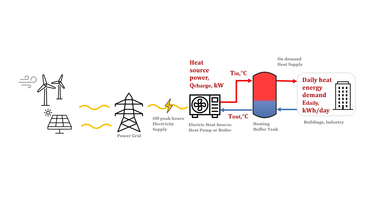
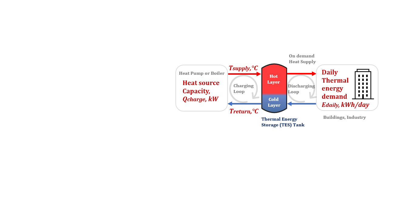
To get started, you just need to know heat source nominal capacity, the selected heating system temperature regime (Tin/Tout), and Daily heat energy demand.
Online Heating Buffer Tank Sizing Calculator

- Gross Heating Buffer Tank Volume (m³)
- Required Charge Time (h)
- Project Feasibility Status
- Recommended Ready-to-Use Tank Capacity
Heating Buffer Tank Sizing Calculator Notes
1. Calculations are performed using the metric unit system.
2. The required storage volume is based on 24-hour heat demand.
3. Water is assumed to be the heat storage medium.
4. Inlet temperature (Tin) shall be up to 130°C.
Outlet temperature, Tout, shall be lower than Tin.
5. Formula used:
Base equation:
Q = ρ · cp · V · ΔT
Q – thermal energy to be stored, kWh (×3600 to convert to kJ),
V= V_useful — required useful (working) volume, m³
ρ, cp — density and specific heat of water, standard reference values
ΔT = Tin − Tout — working temperature difference, calculated automatically
Tin (°C) — Supply temperature, Flow temperature at the tank inlet, entered directly
Tout (°C) — Return temperature, Return temperature at the tank outlet, entered directly
Tank working volume (used to size the tank in this calculator):
V_useful = Q / (ρ · c · ΔT) = E_daily × k /(ρ · cp · ΔT) = E_design / (ρ · cp · ΔT)
Q = E_design (kWh) — Design daily heat energy demand (with margin)
E_design= E_daily × k (this is ‘Q’ in the base equation)
E_daily (kWh/day) — Daily heat energy demand — Total thermal energy to be stored and supplied per day, entered directly
k – Safety margin, k=1.05 — Covers tank/pipe heat losses, load unevenness, piping
Gross (geometric) tank volume, V_gross (m³) — actual tank volume to order:
V_gross = V_useful / η = (E_daily × k × 3600) / (ρ × cp × ΔT × η)
η —Stratification efficiency, Usable fraction of the total geometric volume η = 0.90 for well-designed tanks with diffusers, lower otherwise
Required charge time, t_charge (h) = E_design / Q_charge — time needed to charge the daily demand at
Q_charge (kW) — Heat generator power, Nominal/available thermal power of the boiler or heat pump charging the tank, entered directly
6. Calculation Results:
V_gross (m³) — Gross (geometric) tank volume, actual tank volume to order:
t_charge (h) — Required charge time, — time needed to charge the daily demand at Q_charge (Nominal/available Heat generator thermal power)
Status: “OK — fits within 24h” if t_charge <= 24,
“Insufficient power: exceeds 24h” if t_charge > 24
Recommended our Ready-to-Use tank capacity, m³:
7. The calculator’s purpose is to determine the required charging time, t_charge, given a fixed heat generator power Q_charge and the specified daily heat demand E_daily.
8. Tin and Tout are the design supply/return temperatures of the heating circuit connected to the tank.
ΔT is calculated automatically as Tin − Tout; make sure Tin > Tout.
9. Safety margin k accounts for heat losses through the tank walls and unaccounted load unevenness; it is applied to E_daily to get E_design, which drives both volume and charge time.
10. Stratification efficiency η reflects that a real stratified tank never delivers 100% of its volume within the working ΔT — part of the volume is occupied by the thermocline (mixing zone) between hot and cold layers.
Typical values: 0.85–0.92 (vertical tank, H/D>3, with diffusers),0.60–0.75 (horizontal tank or low H/D without diffusers).
Offered Heating Buffer Tank Sizing Calculator uses Stratification efficiency, η = 0,9, because our Heating Buffer Tanks are well-designed tanks with optimal H/D ratio and stratification system with diffusers designed on precision CFD simulation.
The tanks from another manufacturers can have worse Stratification efficiency values and accordingly will require the more Gross (geometric) tank volume, V_gross (m³) to achieve needed Useful volume, V_useful (m³)
11. If t_charge exceeds 24 hours, the generator power Q_charge is insufficient to cover the daily demand within a day — increase Q_charge or reduce E_daily.
12. Round the final tank volume, V_gross, up to the nearest standard size offered by the manufacturer.
If you need any support during the process, please contact our technical support team on [email protected] are will be happy to assist.
Heating Buffer Tank Sizing Calculation Results Note
➢ If the required tank volume exceeds the capacity of the largest available model, consider using two tanks instead of a single tank.
➢ If the selected tank dimensions exceed transportation or site access limitations, consider using two tanks instead of a single tank.
➢ The calculator determines the required thermal storage volume only. Final tank design must additionally consider applicable standards and project-specific requirements, including PED 2014/68/EU and EN 13445 for pressurized tanks, EN 14015 for atmospheric TES tanks, thermal insulation design according to EN 12241 and EN 17956:2024, and operational requirements affecting thermal stratification efficiency.
Choosing the Right Heating Buffer Tank
Choose a Pressurized Heating Buffer Tank when the heating system is closed-loop (sealed).
Choosing the Right Atmospheric Thermal Energy Storage Tank
Choose an Atmospheric Thermal Energy Storage Tank for open or vented heating systems where non-pressurized thermal storage is required.

Heating Buffer Tank Sizing Calculator Accuracy & Disclaimer

Important Disclaimer:
The calculation results provided by our tools are estimates only and are intended for informational and planning purposes.
While we strive to ensure the accuracy and reliability of our calculators, we make no warranties or representations that:
- The calculations will be 100% accurate for your specific project.
- The information is suitable for permitting or regulatory compliance purposes.
- The tools will be available without interruption or be error-free.
- We strongly recommend consulting with a licensed designer or engineering company before making any purchasing or construction decisions based on our calculator results.
Advantages of WTS Heating Buffer Tanks and TES Tanks

Save on:
✔ Tank Design!
✔ Project Design!
✔ Installation!

Faster Decarbonization Projects
Up to 3 months faster
project completion
with prefabricated tanks

Lowest Total Cost of Ownership
Zero corrosion.
Lowest OPEX.
No loss of asset value
over time.

40+ Years Design Lifetime
Our Stainless Steel Tanks
Engineered for
Longest Service Life

Energy Cost Optimization
Store heat when
electricity prices are low
and use it during peak
demand periods

Up to 50% Smaller Installation Footprint
Ideal for Dense Urban
Developments